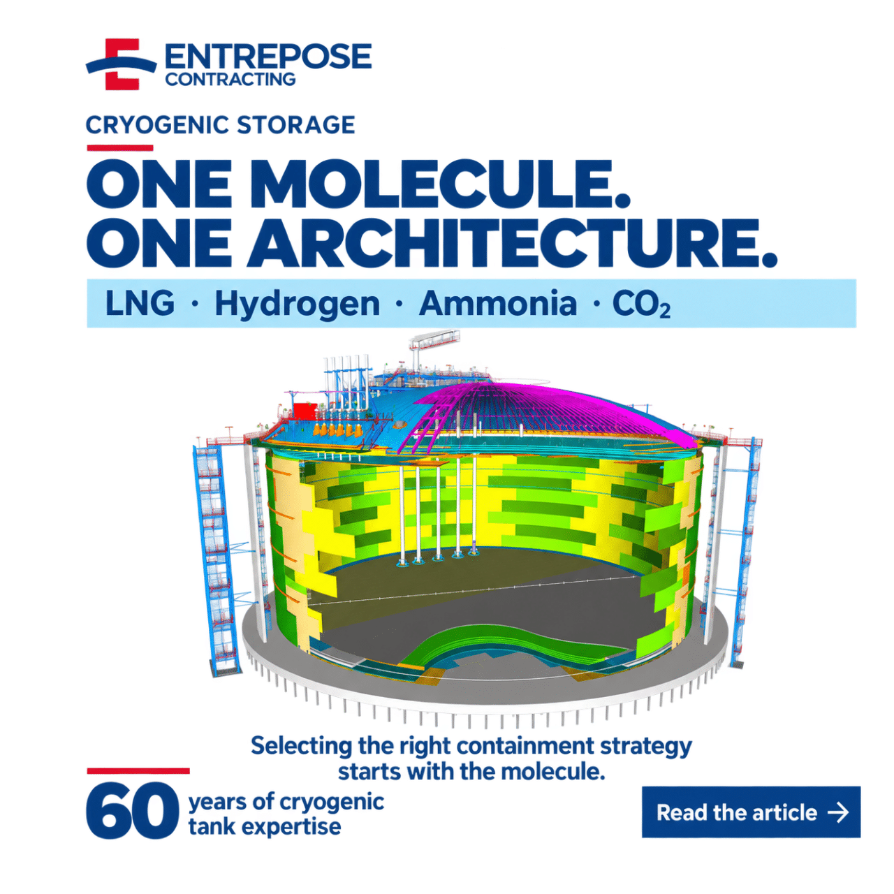
1. CRYOGENIC, REFRIGERATED, OR CONVENTIONAL STORAGE: THREE METHODS THAT SHOULD NOT BE CONFUSED
Conventional storage refers to fluids stored at room temperature, at atmospheric pressure, or at moderate pressure. Refrigerated storage lowers the temperature to liquefy the product, without entering the cryogenic range. Cryogenic storage, on the other hand, operates at extreme temperatures—from −162 °C (LNG) to −253 °C (liquid hydrogen). At these temperatures, ordinary steels become brittle, even the slightest heat input causes evaporation, and the safety of the containment system becomes the central concern of the entire design.
Liquefying a gas significantly reduces its volume—by a factor of about 600 for natural gas—and makes it transportable and storable. But this densification has an inevitable trade-off: boil-off gas (BOG). No matter how good the insulation is, a residual heat flux always penetrates the tank and vaporizes a fraction of the liquid. A cryogenic tank is therefore never inert: it is a steady-state thermodynamic system, and its pressure, stratification, and evaporation must be controlled throughout the structure’s entire service life.
Designing a structure like this involves distributing three functions that technology tends to separate: liquid and vapor tightness, thermal insulation, and structural strength. It is the way these functions are distributed among the components that distinguishes the major architectural styles—we will return to this later.
Founded in 1935, Entrepose Contracting draws on nearly a century of experience and approximately 100 projects to carry out complex cryogenic projects. This expertise was not built on principles, but on specific physical constraints: 9% nickel steel at −163 °C, prestressed concrete under cryogenic loads, and thermal cycle management
2. THE MOLECULE DETERMINES THE DESIGN
There is no such thing as a “generic” cryogenic tank that can be adapted with minor adjustments. Temperature, pressure, density, thermodynamic behavior, risk of boil-off, material compatibility, and safety profile: for each molecule, these parameters dictate a distinct design. Assuming that expertise can be applied directly from one fluid to another leaves one vulnerable to costly errors.
LNG (−162 °C): the atmospheric reference
Liquefied natural gas remains the benchmark application for large-capacity cryogenic storage. At −162 °C and near-atmospheric pressure, it is stored in tanks consisting of an inner vessel made of 9% nickel steel—which retains its ductility at very low temperatures—and an outer shell made of prestressed concrete. Three key challenges stand out: containment safety, structural resilience, and control of evaporation losses, which are managed through reliquefaction or the recovery of boil-off gas.
Liquid hydrogen (−253 °C): a paradigm shift
Liquid hydrogen is a game-changer. At −253 °C, it is far more sensitive to heat input than LNG: converting an LNG tank to a flat-bottom design simply doesn’t make sense. The solutions rely on double-walled, vacuum-insulated tanks—spheres or cylinders—whose extreme insulation limits boil-off. The cryogenic foundation gained from LNG (calculation methods, welding qualifications, material behavior) remains useful, but it must be re-evaluated, not simply copied. That is where the difference lies.
Ammonia (−33 °C): Toxicity Takes Precedence Over Temperature
Ammonia (NH₃), which liquefies at approximately −33 °C at atmospheric pressure, lies on the border of the cryogenic range. Its design-limiting factor is not the cold, but its toxicity, which requires a high level of containment. The question of conversion often arises: an LNG tank can, under certain conditions, be adapted for ammonia storage—but this conversion is never without consequences. Submersible pumps, level and density gauges, valves, and instrumentation must be re-certified or replaced, and material compatibility must be re-verified. A low-carbon ammonia project must therefore decide early on between a design built specifically for ammonia and conversion.
Liquid CO₂ (CCUS): The Challenge of the Triple Point and Impurities
As a key component of carbon capture, utilization, and storage (CCUS) systems, liquefied CO₂ exhibits unique physical properties. It can only be liquefied above its triple point (5.18 bar, −56.6 °C): storage therefore takes place under pressure, in tanks operating near this limit, with a risk of dry ice formation in the event of a pressure drop. Impurities from the source and the capture technology alter the product’s properties (phase boundaries, density) and increase the risk of corrosion. In the absence of a harmonized international standard, the decision between low and medium pressure is made on a project-by-project basis, depending on the actual composition of the stream and the intended supply chain.
EXPERT ADVICE
Converting an LNG tank to ammonia storage: what needs to be re-certified
The compatibility of 9% nickel steel with ammonia is not sufficient to validate a conversion. Internal equipment—pumps, level and density gauges, relief valves, and instrumentation—is sized for LNG and must be reviewed. The toxicity of NH₃ also shifts the risk analysis toward specific dispersion scenarios. An unplanned conversion poses a risk to integrity and compliance: it must be treated as a full-fledged engineering project, not as a minor modification.
EXPERT ADVICE
Liquid CO₂: Why Impurities Change the Design
Unlike LNG, whose composition is relatively stable, the CO₂ stream from capture varies depending on the source (post-combustion, oxy-combustion, direct capture). Nitrogen, oxygen, water, sulfur oxides, and nitrogen oxides shift phase boundaries, increase saturation pressure, and promote acid corrosion in the presence of free water. The tank design and choice of materials can therefore only be finalized once the purity specification for the stream has been established—often defined by contract between the seller, the transporter, and the storage site operator.
3. THREE CONFINEMENT ARCHITECTURES, ONE CRITERION: THE PROJECT’S BENEFIT
Unlike LNG, which has a relatively stable composition, the CO₂ stream from capture varies depending on the source (post-combustion, oxy-combustion, direct capture). Nitrogen, oxygen, water, sulfur oxides, and nitrogen oxides shift phase boundaries, increase saturation pressure, and promote acid corrosion in the presence of free water. The tank design and choice of materials can therefore only be finalized once the purity specification for the stream has been established—often defined by a contract between the seller, the transporter, and the storage site operator.
- Single containment: a liquid-tight primary vessel, an outer shell that protects the insulation and contains the steam, and a retention tank serving as a second barrier. Lowest capital expenditure, but requires a large footprint and entails increased exposure to external hazards.
- Double containment: a secondary wall adjacent to the primary vessel, capable of containing the liquid in the event of a leak, but without controlled vapor containment. Requires less space than single containment.
- Full containment: a primary vessel made of 9% nickel steel and a secondary containment structure—most often made of prestressed concrete—each capable of independently containing the liquid; the containment structure also ensures controlled vapor release and resists external impacts. This is the standard for large terminals: a smaller footprint and a higher level of safety